
From Science Fiction to Reality
Controlling machines with our minds was once the stuff of science fiction. Today, Brain-Computer Interfaces (BCIs) are transforming that fantasy into reality, bridging the gap between neurological activity and digital systems. BCIs enable direct communication between the brain and external devices, opening up new possibilities in technology and human interaction.
You might think this technology requires expensive equipment and specialized labs. Surprisingly, you can build your own BCI at home! In this guide, we'll walk you through constructing a custom BCI using the OpenBCI Ultracortex headset frame, a PiEEG board, Conscious Labs ThinkPulse Electrodes, and a Raspberry Pi.
What You'll Need:
- 3D Printer: For printing the Ultracortex headset frame.
- PLA Filament: Material for 3D printing.
- Ultracortex STL Files: 3D models for the headset.
- Raspberry Pi (4 or 5): The main processor.
- PiEEG (8 or 16 channels): EEG acquisition board.
- Conscious Labs ThinkPulse Electrodes: Active dry electrodes.
- PiSugar2 Pro Battery: Portable power solution.
- Raspberry Pi Case (with HAT support): Enclosure for the Raspberry Pi and PiEEG.
- Power Distribution Board: For distributing power to electrodes.
- Braided Cable Sleeve: Organizes and protects wiring.
- Pre-Crimped Jumper Cables: For connecting components.
- Dupont Wire Crimping Kit: For creating custom cables.
- Heat Shrink Tubing: Insulates and protects connections.
Tip: Ensure you have a steady supply of patience—building BCIs requires attention to detail and troubleshooting along the way.
Getting Started: Capturing Brainwave Data in Real Time
Before diving into the construction of your BCI, it's essential to understand how we'll acquire brainwave data. Our goal is to build a non-invasive system that functions reliably in various environments. It needs to record a user's brain signals in real time and translate them into data a computer can interpret. To achieve this, we'll leverage a technology called Electroencephalography (EEG).
Did You Know? Electroencephalography (EEG) was invented by Hans Berger in 1924. He was the first to record brainwaves, coining the term "electroencephalogram" to describe the electrical activity he observed in the human brain. His pioneering work laid the foundation for modern neuroscience and the development of BCIs.
What Is EEG and Why Is It Essential for Modern BCIs?
Electroencephalography (EEG) is a technique for recording the electrical activity generated by neurons in the brain. It's the most widely used tool in BCIs because it offers a non-invasive method to monitor brain function. EEG signals are captured through electrodes placed on the scalp, detecting tiny voltage fluctuations resulting from neuronal firing. The real-time recording capability of EEG makes it invaluable for BCIs, providing immediate feedback on brain activity.
In clinical and research settings, EEG is commonly used to study brain disorders such as epilepsy, sleep disturbances, and stroke recovery. For BCIs, EEG is favored because it allows direct monitoring of brain activity without surgical intervention, making it accessible to a wide range of users. While EEG has limited spatial resolution—meaning it can't precisely pinpoint where neural activity originates—it excels in temporal resolution, capturing rapid changes in brain activity. This is crucial for BCIs that require immediate brainwave data to interact with external devices in real time.
The Science of Brainwaves: Decoding Alpha, Beta, and Gamma Waves
EEG captures a spectrum of brainwave frequencies, each linked to different mental states and cognitive functions. These brainwaves are classified into five primary frequency bands:
- Delta Waves (0.5–4 Hz): Slow waves associated with deep, restorative sleep and unconscious processes.
- Theta Waves (4–8 Hz): Linked to creativity, intuition, and deep relaxation; often observed during light sleep or meditation.
- Alpha Waves (8–13 Hz): Indicative of a calm and relaxed state, usually when the eyes are closed and the mind is at ease but alert.
- Beta Waves (13–30 Hz): Present when the brain is engaged in active thinking, problem-solving, and focused mental activity.
- Gamma Waves (30–100 Hz): The fastest brainwaves, associated with high-level information processing, learning, and integrating sensory inputs.
For our BCI build, we'll concentrate on alpha, beta, and gamma waves due to their relevance in cognitive tasks, focus, and relaxation states. These brainwaves are particularly useful for applications involving attention management, cognitive load assessment, and neurofeedback systems.
Pro Tip: While EEG excels at capturing the timing of brain activity (temporal resolution), it has limitations in pinpointing the exact location (spatial resolution). This makes precise electrode placement crucial for obtaining accurate and meaningful data.
Choosing the Right Components for Your BCI Build
Selecting appropriate components is critical for building an effective BCI. We'll need electrodes to capture brain signals and a central processor to read and interpret them. The electrodes must be securely positioned on the user's scalp to ensure reliable data collection. This guide focuses on the following key components:
The Ultracortex Frame
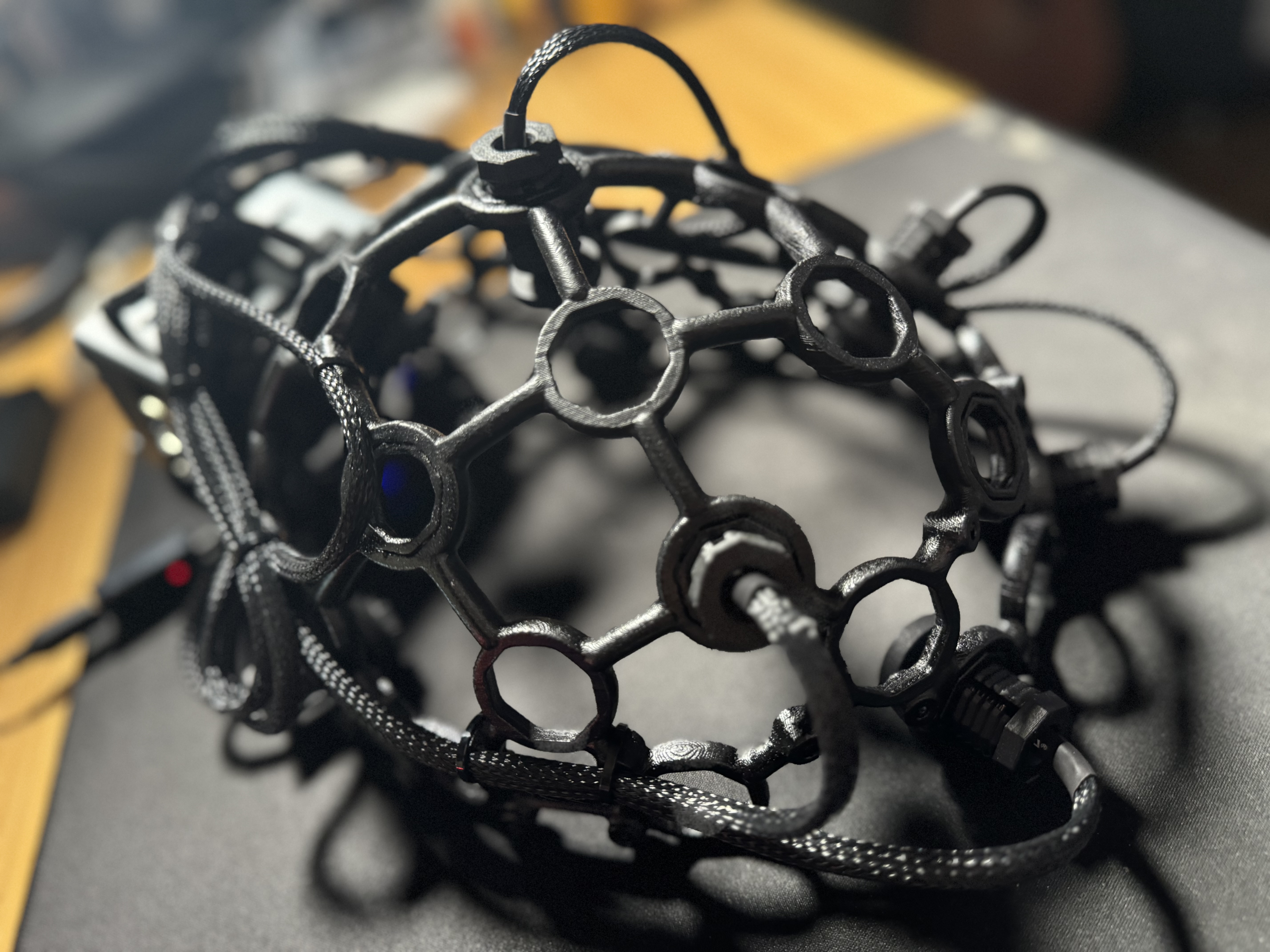
The OpenBCI Ultracortex headset frame is a modular, 3D-printable design that allows for easy customization. Its open-source nature means you can modify or replace parts to suit your specific needs, whether for research or personal projects. The frame is designed to hold the electrodes in precise positions, ensuring optimal contact with the scalp.
ThinkPulse Electrodes
Conscious Labs ThinkPulse Electrodes are active dry electrodes, meaning they are powered and do not require conductive gel. These electrodes offer reliable signal quality without the inconvenience associated with traditional wet electrodes. They are user-friendly and ideal for home BCI projects.
Note: Dry electrodes may be more susceptible to noise compared to wet electrodes. Ensure proper contact with the scalp to achieve accurate readings.
PiEEG Board
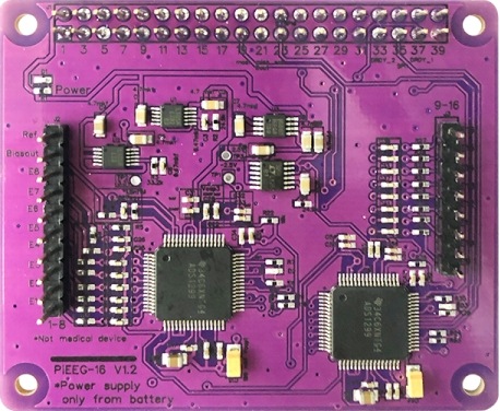
The PiEEG is an EEG data acquisition board designed to interface directly with the Raspberry Pi's GPIO pins. This seamless integration allows the Raspberry Pi to read the low-voltage signals from the EEG electrodes and process them in real time. The PiEEG supports multiple channels, enabling data collection from several electrodes simultaneously.
Alternative Option: An OpenBCI Cyton board can be used instead of the PiEEG. For more details, visit the OpenBCI Store.
Build Walkthrough: 3D Printing & Assembly
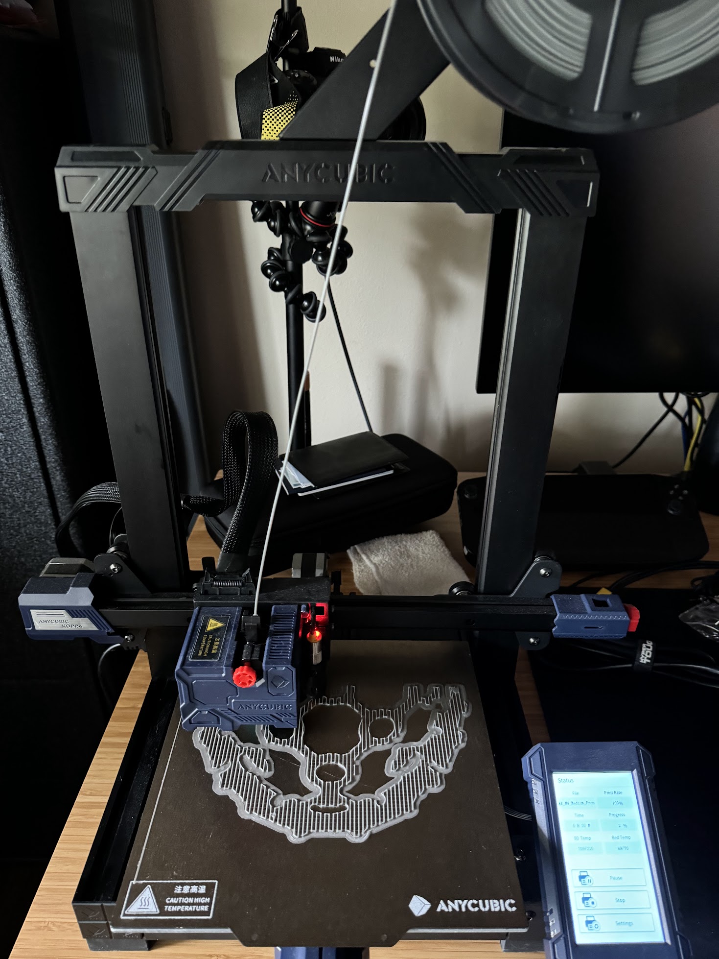
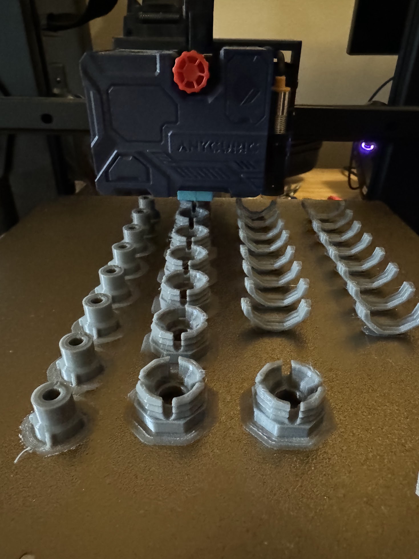
The first step in our BCI build is to print the Ultracortex frame and necessary parts. Using a 3D printer like the AnyCubic Kobra, we can produce custom parts, allowing complete control over the fit and design of the headset. If you don't have a 3D printer or prefer not to print the frame yourself, you can purchase a completed print from the OpenBCI store.
1. Material Selection
We used ANYCUBIC PLA filament 1.75mm, which is strong yet lightweight—ideal for wearable devices. PLA is beginner-friendly for 3D printing, but materials like PETG can be considered for added strength.
Tip: Choose a filament with a good balance between strength and flexibility, especially for wearable tech.
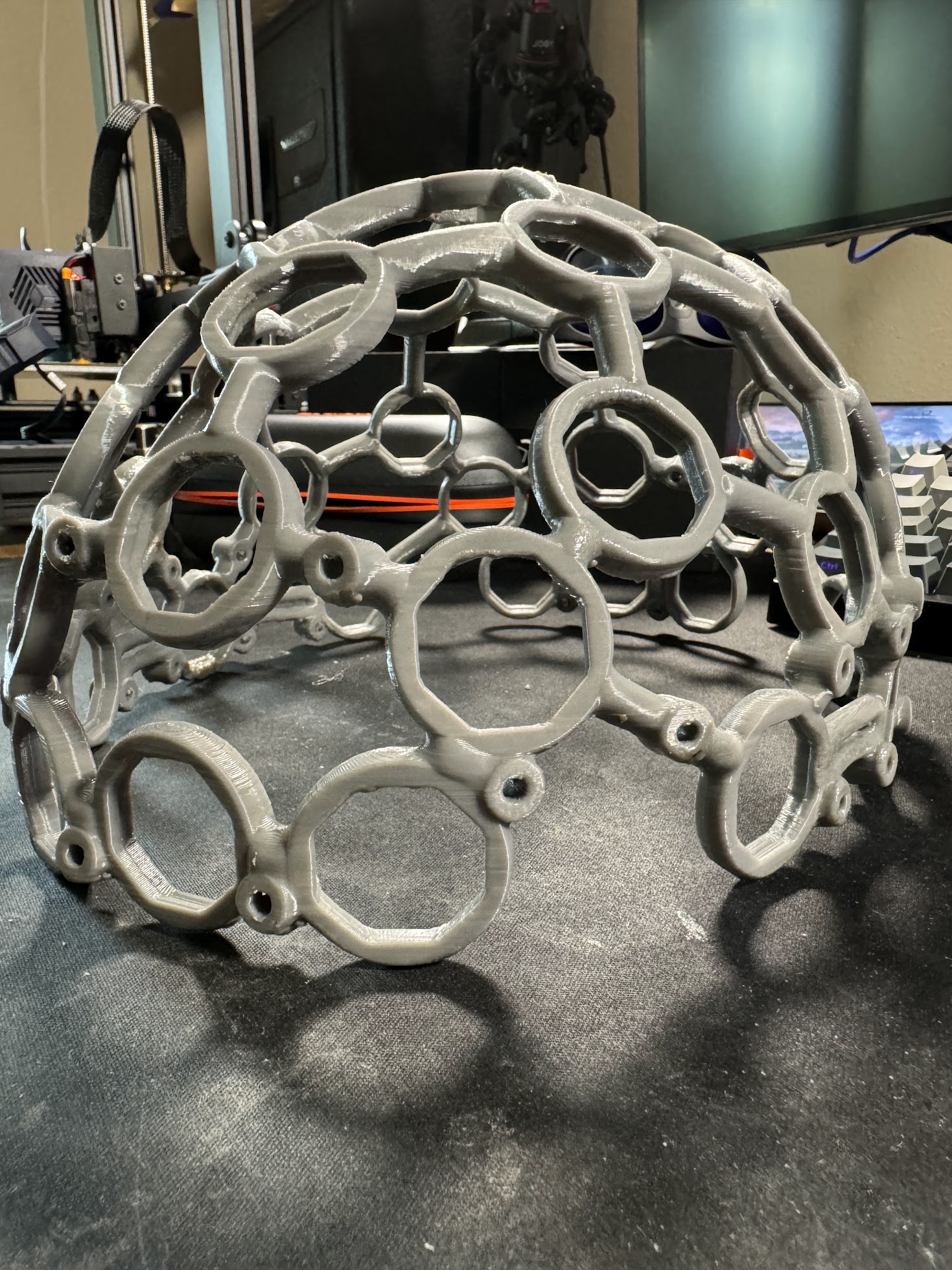
2. Printing the Frame
Download the Front and Back .STL files from the OpenBCI GitHub repository. Select small, medium, or large based on your head circumference:
- Small: 42–50 cm
- Medium: 48–58 cm
- Large: 58–65 cm
Note: The Ultracortex can also be printed in one piece if your printer supports the size.
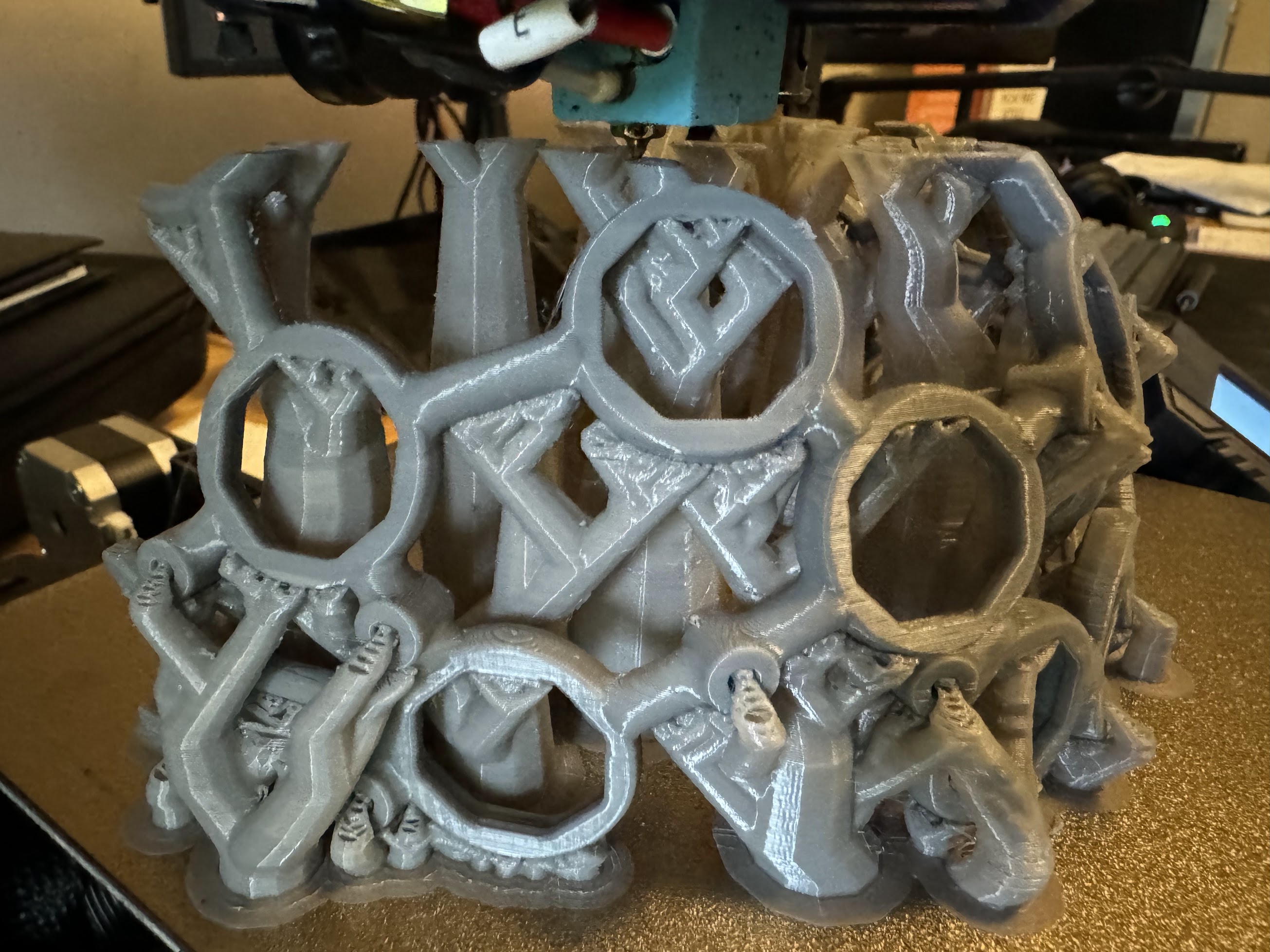
Print settings vary by printer. The minimum build area needed to print the frame in halves is 130 mm x 210 mm. This print requires support structures. Due to the model's complexity, a slower print speed (50%) is recommended.
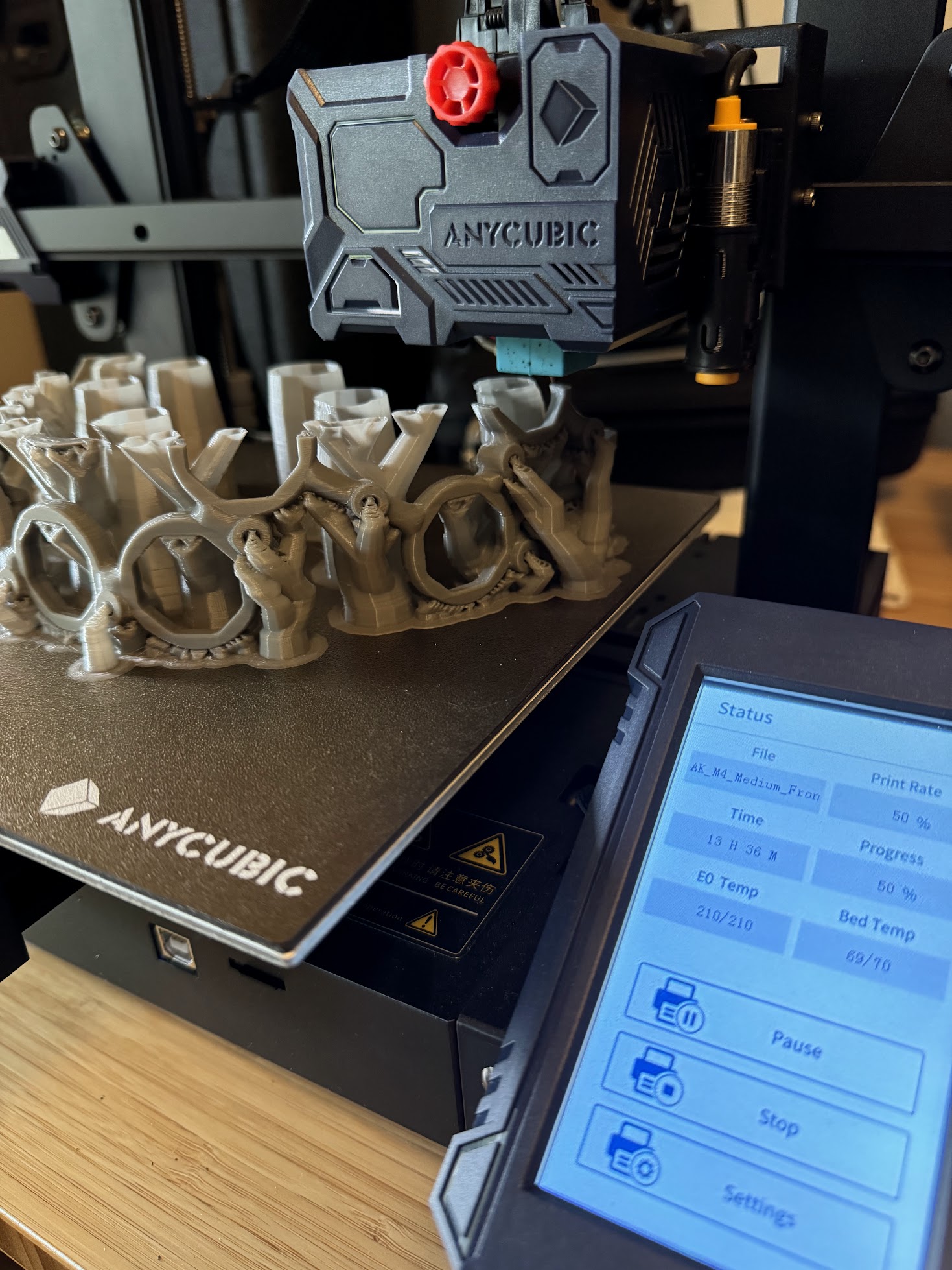
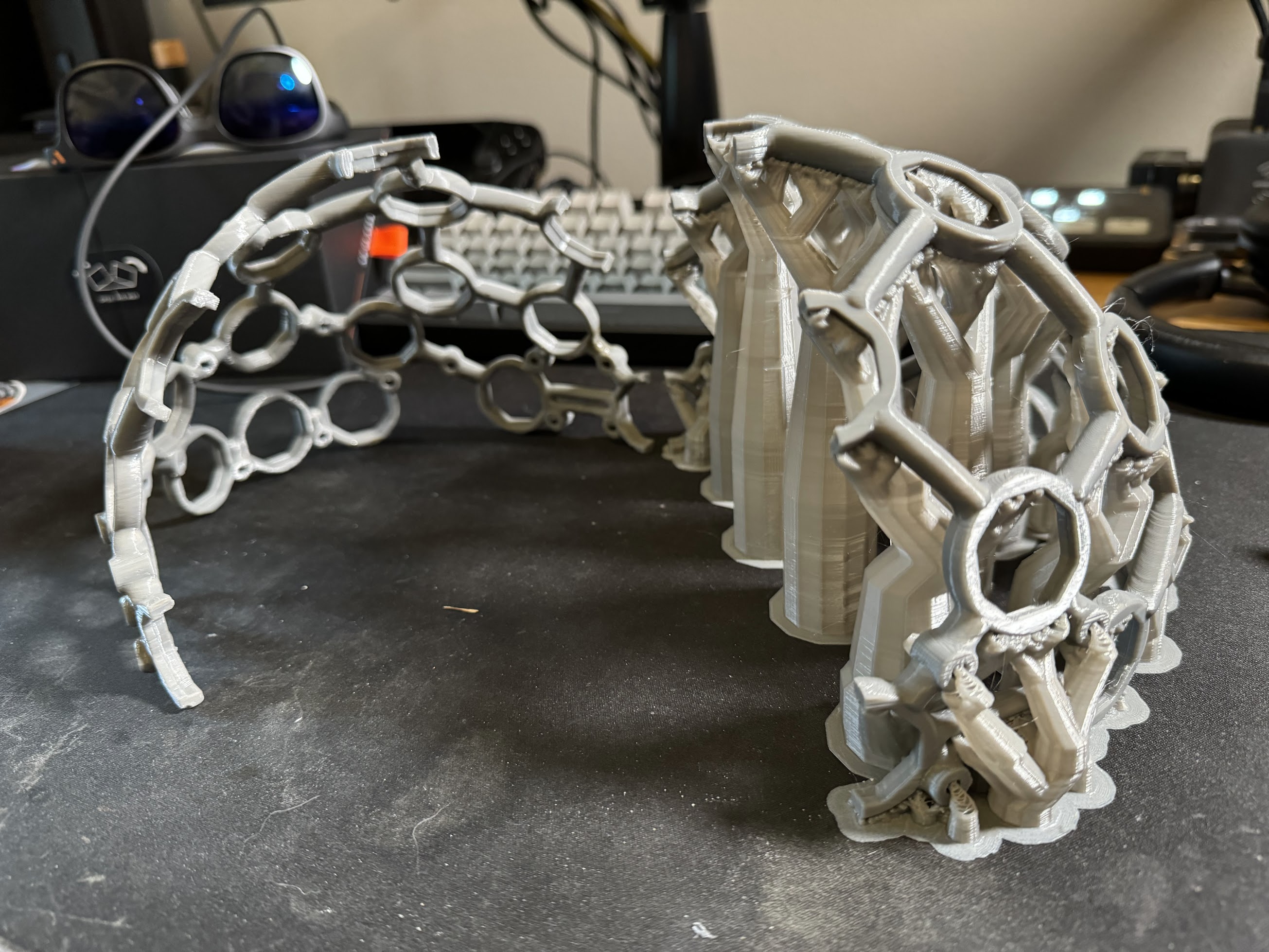
Time-Saving Tip: Printing the Ultracortex can take 48 hours or more. While you wait, proceed to the next steps to prepare for assembly.
3. Printing Electrode Screws and Mounts
After printing the frame, download and print the Electrode Screws (Octabolt) and Screw Mounts (Eholder). These small parts require precise printing and are crucial for maintaining proper contact with the scalp.
Note: Remove any support material carefully and sand the finished prints with fine-grit sandpaper for a smooth finish.
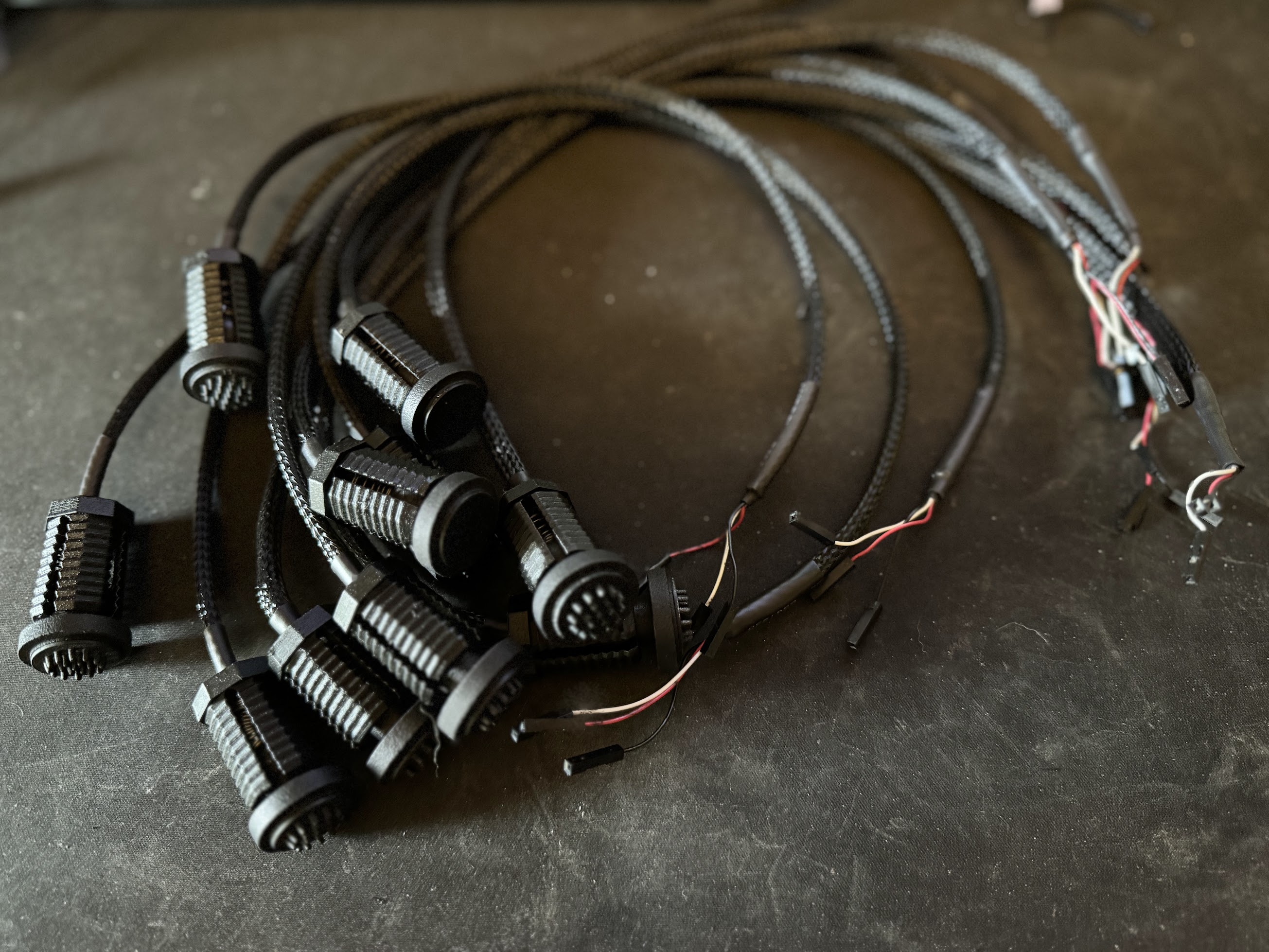
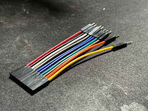
4. Creating Custom Jumpers and Power Distribution
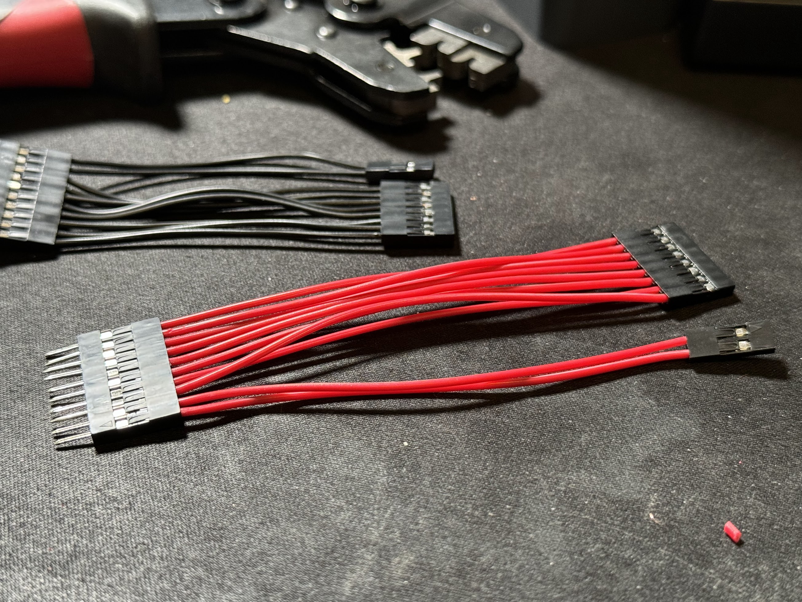
To simplify connections and maintain modularity, we created custom color-coded jumper wires to extend the PiEEG board pins out of its enclosure. Color-coding each wire corresponding to a specific electrode makes troubleshooting and identification easier. We'll use the same color scheme in our software for visualizing brainwave signals.
A Power Distribution Board distributes power from the Raspberry Pi's GPIO pins (GPIO 1 for positive and GPIO 5 for negative) to each electrode.
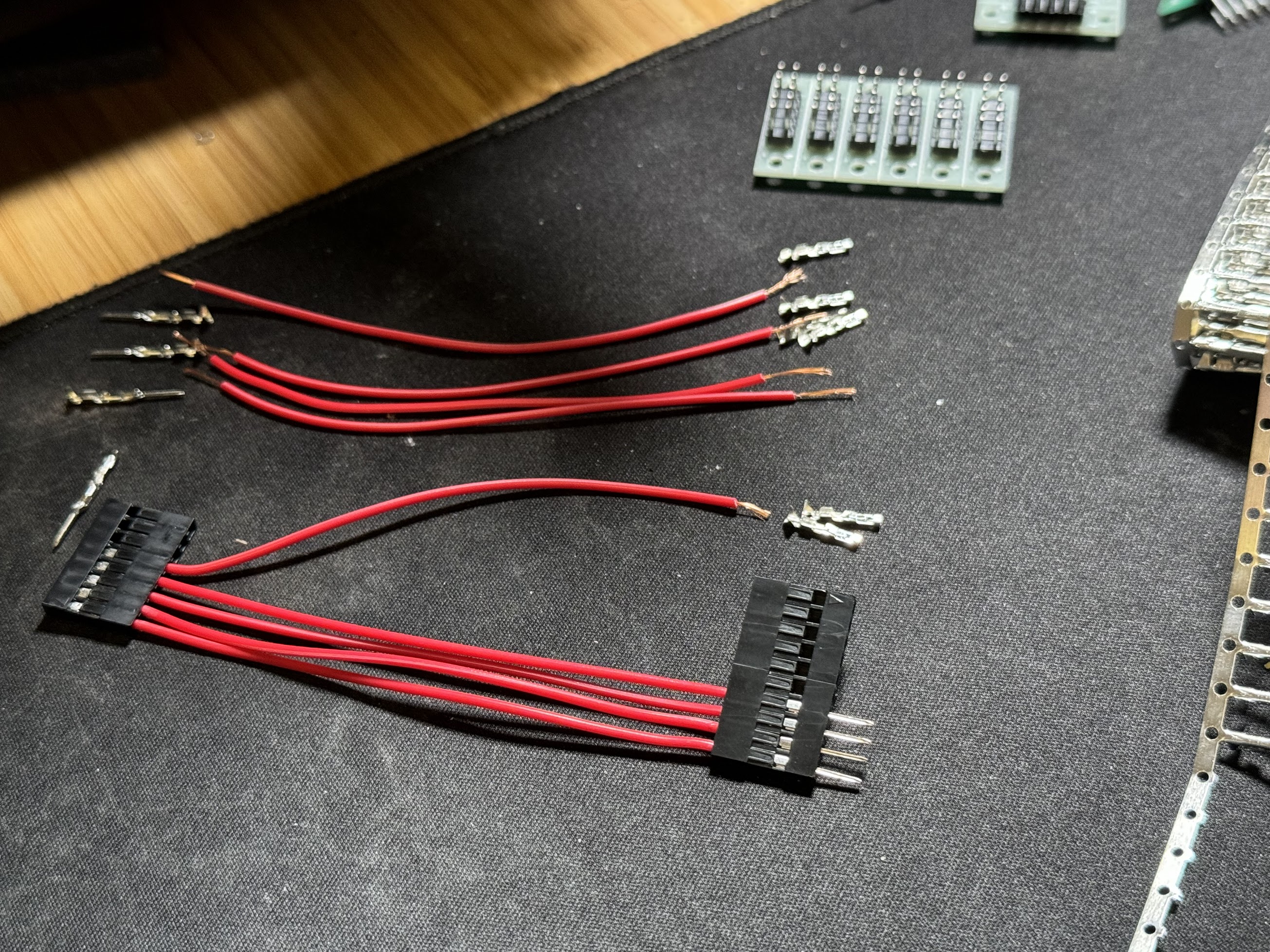
Custom red and black jumper wires connect each electrode to the power distribution board, which is neatly concealed.
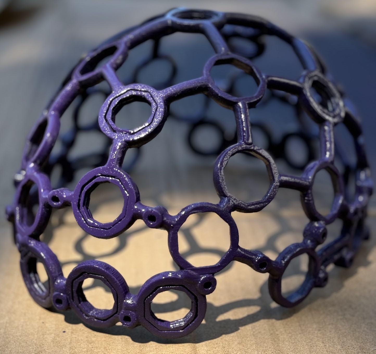
5. Assembling and Finishing the Ultracortex Frame
Once the frame and parts are printed, carefully remove all support material and sand the surfaces with fine-grit sandpaper to prepare for painting.
- Assembly: Align the front and back pieces of the frame and secure them with super glue. Allow the glue to dry thoroughly.
- Mounting Screw Holders: Insert the Electrode Screw Mounts into the frame at desired electrode positions and secure with super glue.
Note: A final sanding may be needed after the glue sets to ensure a smooth finish.
Choose a quality spray paint that fits your desired aesthetic. Move the frame and small parts to a well-ventilated area prepared for painting. Apply multiple thin coats, allowing each to dry before the next.
Painting Tip: Minimize paint on the Electrode Screws and Screw Mounts to avoid interfering with their function.
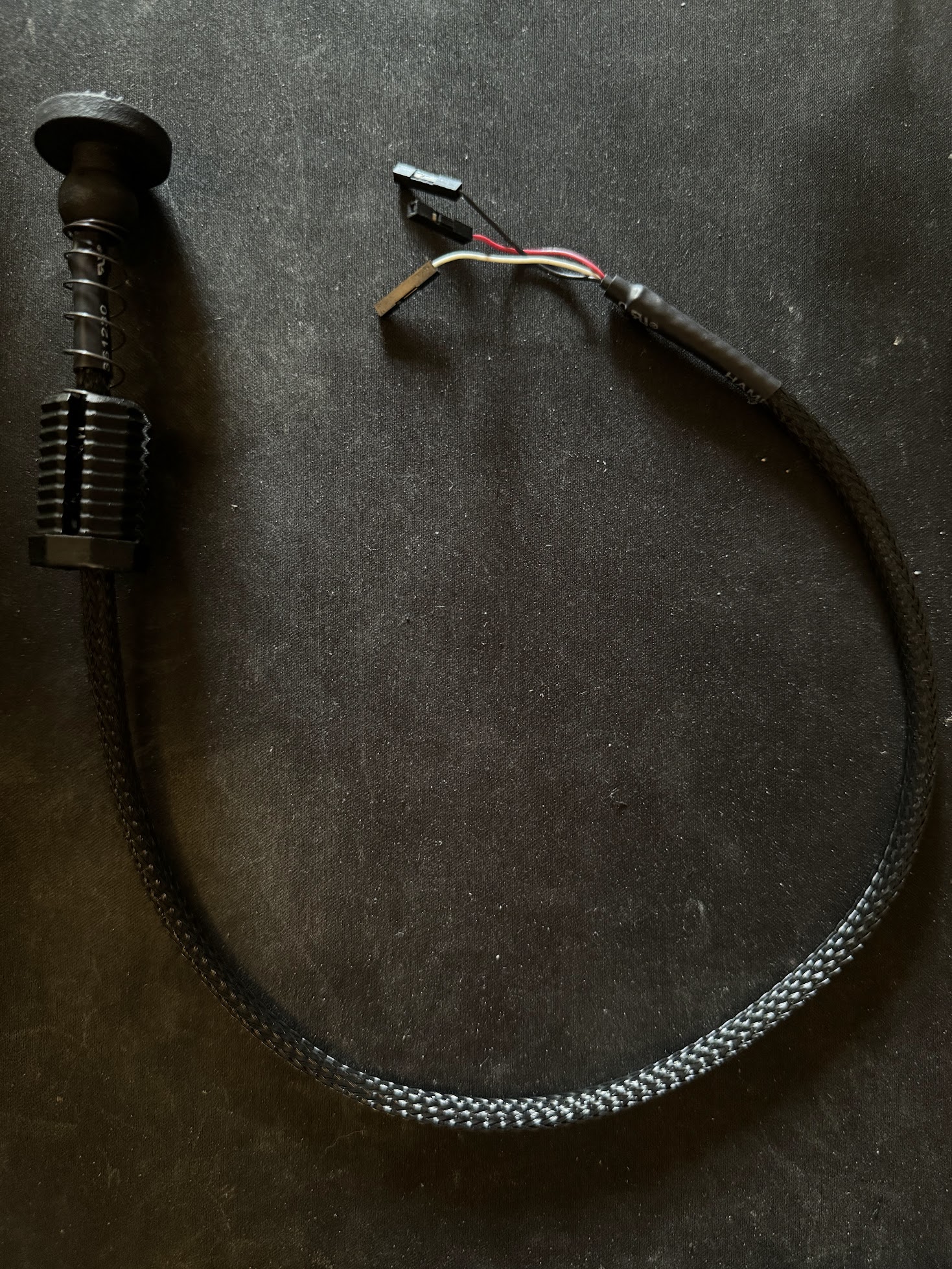
6. Electrode Assembly and Custom Sleeves
The ThinkPulse Electrodes are inserted into the 3D-printed Electrode Screws with small springs (not included but easily sourced). The assembled electrode and screw are then inserted into the Ultracortex frame during final assembly.
To enhance the aesthetic, we used braided cable sleeves to cover the electrode wires. This not only improves appearance but also organizes the cables. Heat shrink tubing secures the ends.
Note: After cutting the cable sleeve, quickly melt the ends with a lighter to prevent fraying during assembly.
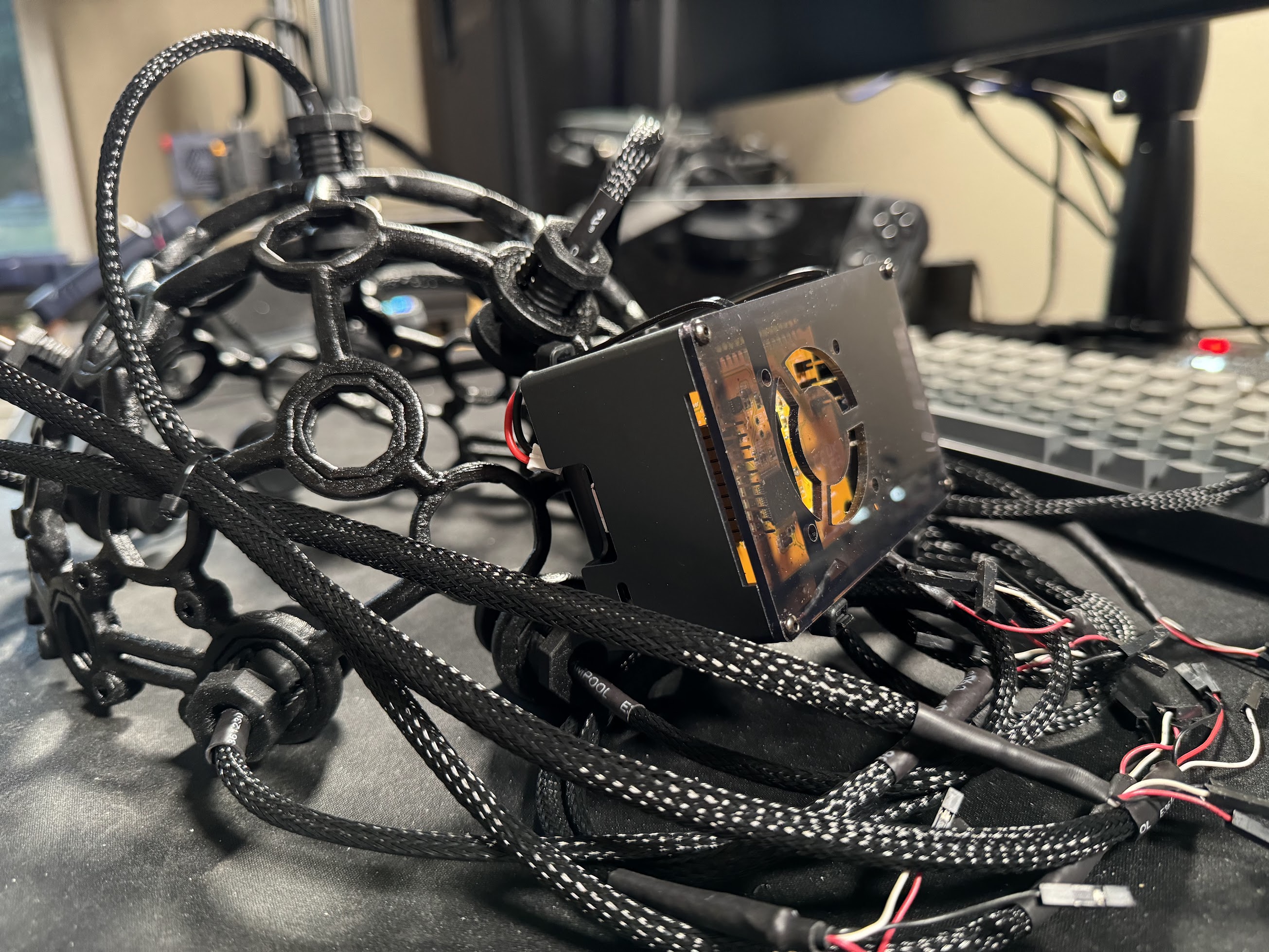
7. Installing the PiEEG Board
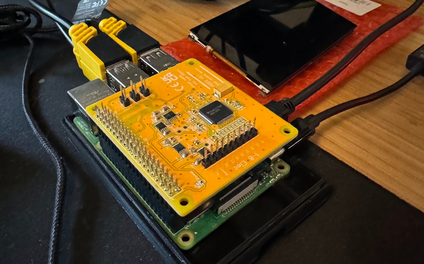
Attach the PiEEG directly to the Raspberry Pi's GPIO pins, ensuring each pin is securely connected. This setup allows the Raspberry Pi to read and process EEG signals in real time.
For mobility and reduced signal noise, use a battery like the PiSugar2 Pro instead of USB power. Install the Raspberry Pi and PiEEG into a case that supports a HAT. Secure the case to the Ultracortex frame using screws or zip ties.
Power Tip: The PiSugar2 Pro conveniently attaches to the bottom of the Raspberry Pi, providing a compact power solution.
8. Electrode Installation and Wire Management
Finish the assembly by screwing the electrode assemblies into their mounts and organizing the wires neatly along the frame.
Optimizing Electrode Positioning for Accurate Data Collection
Electrode placement is crucial for capturing meaningful EEG data. We'll use the 10-20 system, a standard method that positions electrodes relative to key landmarks on the skull, ensuring symmetry and coverage of important brain regions.
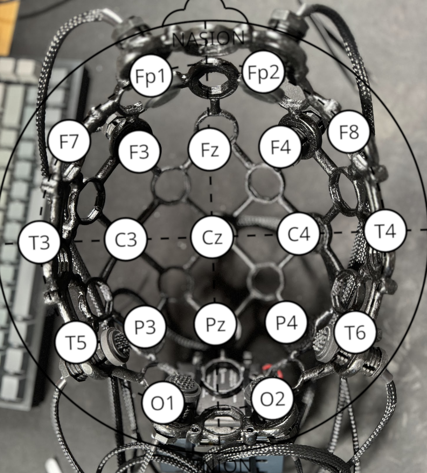
Key landmarks:
- Nasion: The point between the forehead and the nose.
- Inion: The bump on the back of the skull.
- Cz: Central point at the top of the skull.
The 10-20 system covers regions associated with various cognitive functions:
- Frontal Region (Fp1, Fp2, F3, F4, F7, F8, Fz): Decision-making, problem-solving, planning, and focus.
- Central and Parietal Region (C3, C4, Cz, Pz, P3, P4): Sensory processing and motor functions.
- Temporal Region (T3, T4, T5, T6): Auditory processing and memory.
- Occipital Region (O1, O2): Visual processing.
The modular Ultracortex frame allows easy adjustment of electrode positions to suit different applications.
Organize the wires towards the back of the BCI, connecting the signal jumper cables to the corresponding pins on the PiEEG. Use GPIO pin 1 (+) and GPIO pin 5 (-) to power the electrodes via the power distribution board. Neatly position the wires and power distribution board into the Pi case.
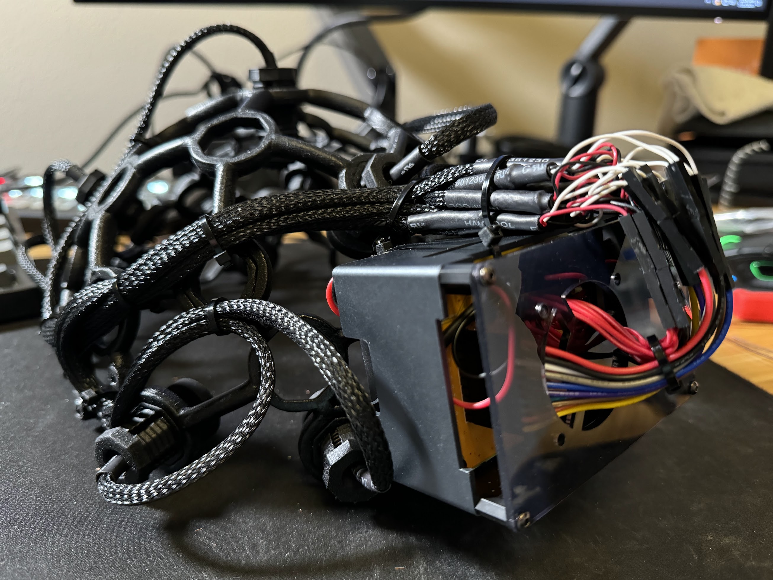
Once assembled, your BCI is complete and ready for testing.
Conclusion: The Road Ahead
Building your own BCI is an exciting journey that merges neuroscience with technology. Through this process, you've gained insights into how brainwaves can be captured, processed, and used for various applications. Whether for cognitive enhancement, research, or health monitoring, this project is a gateway to the future of brain-computer interaction.
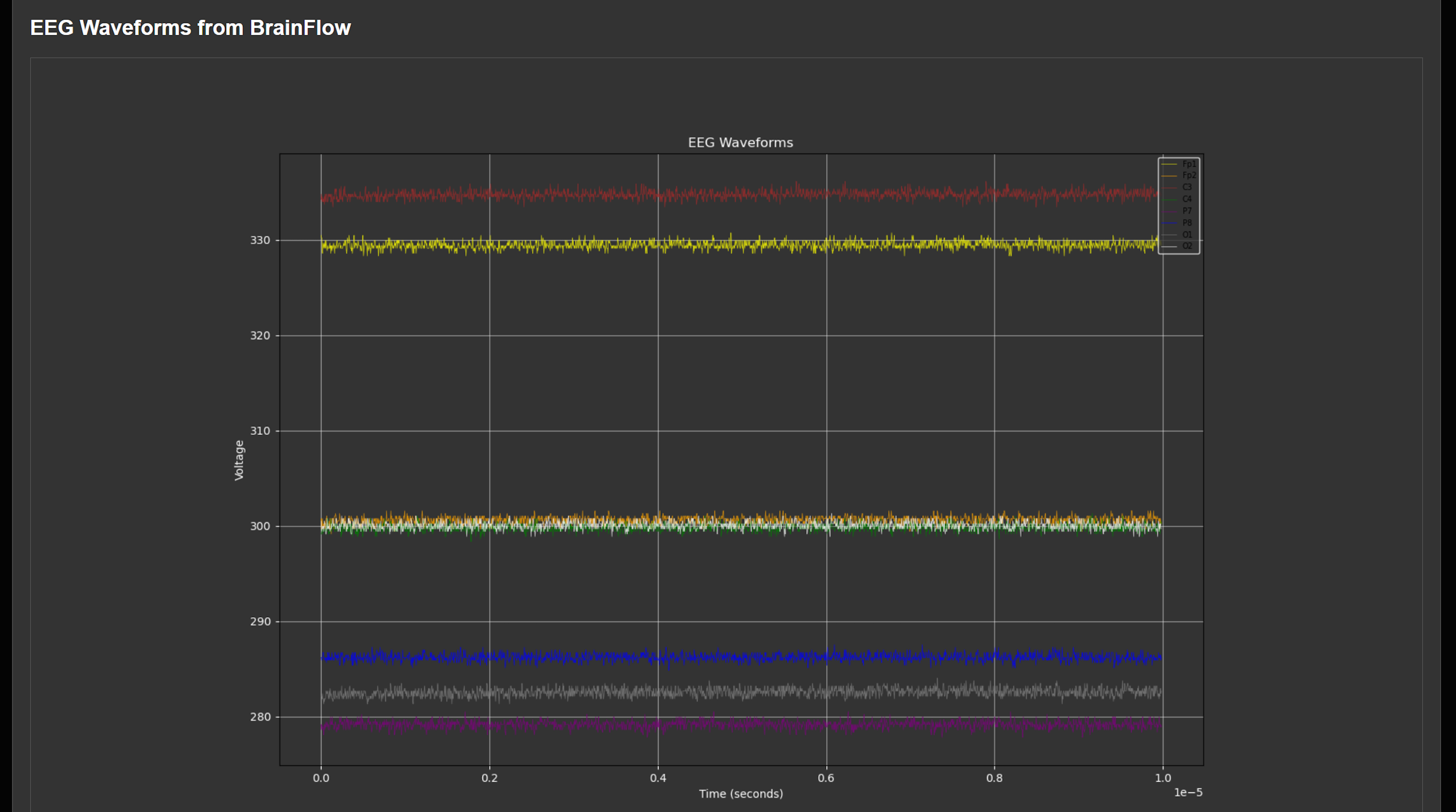
Next Steps: Now that you have a working BCI, its time to build an Advanced Real-Time EEG Analysis App with Flask and BrainFlow.